
Regular Network Architecture
Backbone Infrastructure
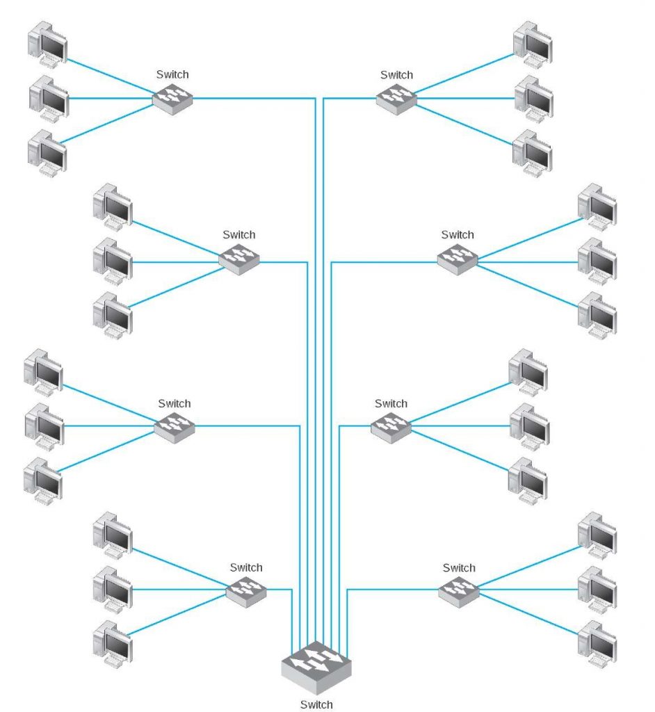
The Internet is made up of many local networks (LANs) connected to each other. These networks are combined by Internet service providers. Companies like Turkcell, Vodafone, Turktelekom are internet service providers in Turkey. ISP. These networks then connect to the larger Global ISP networks, than to telecommunication-wireless(LTE/NR) networks and industry networks. In this way, all network clusters are connected with this structures called Backbone. Below is the scheme of the BackBone network. This is called by backbone because it looks like a backbone structure.
OSI Model And Regular Network Stack

Layer 1 – Physical Layer Functionality
The physical layer is responsible for the transmission and reception of unstructured raw data bit steam between devices. Physical Layer is on hardware level. It provides hardware peer to peer communication.
Layer 2 – MAC Layer Functionality
The MAC layer is responsible for managing of accessing channel. It provides access mechanism to single channel for multiple devices. It needs connection topologies and channel access algorithms like TDMA, ALOHA, FDMA etc…
Layer 3 – Network Layer Functionality
The Network layer is responsible for managing and accessing of network. The part of the Internet communications process where these connections occur, by sending packets of data back and forth between different networks. Handles the routing and sending of data between different networks. The most important protocols at this layer are IP and ICMP.
Layer 4 … – Transport Layer And So On…
- 4. Transport layer: Provides the means for transmitting data between the two connected parties, as well as controlling the quality of service. The main protocols used here are TCP and UDP.
- 5. Session layer: Controls connections between computers (this can also be handled at layer 4 by the TCP protocol).
- 6. Presentation layer: Data is translated into a form the application can accept. Some authorities consider HTTPS encryption and decryption to take place at this layer.
- 7. Application layer: Data generated by and usable by software applications. The main protocol used at this layer is HTTP.
4G/LTE Network Architecture
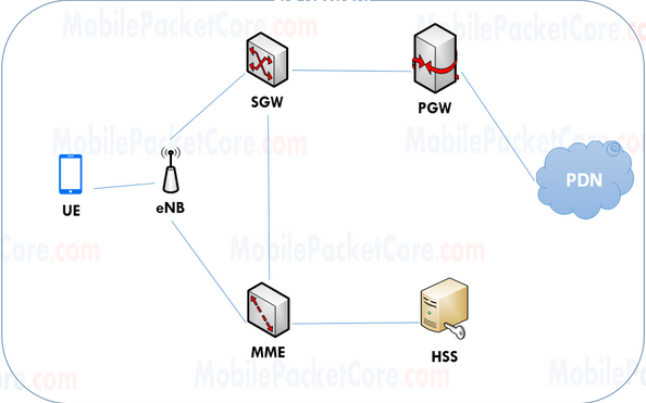
- eNodeB is 4G site that UE connects to. It provides radio interface to the UE
- MME refers to Mobility Management Entity. It is responsible to Authenticating UE. In Addition, It tracks the location of UE. So, It selects the suitable SGW and PGW that serve to UE.
- SGW refers to ‘Serving Gateway’ In order to eliminate any effect on user data while the UE moves between different NodeBs, the SGW works as an anchor point for user data of the UE, while the UE is moving between different eNodeBs. In addition, the SGW forwards user data between the eNodeB and the PGW.
- PGW refers to ‘PDN Gateway’. The PGW is the node that connects between the LTE network, and the PDN. (Network BackBone Infrastructure)
- HSS refers to ‘Home Subscriber Server. The HSS is the Database that stores the subscription information of the users in the network, like which PDN they should be able to access, and the QoS they should have, .. etc.
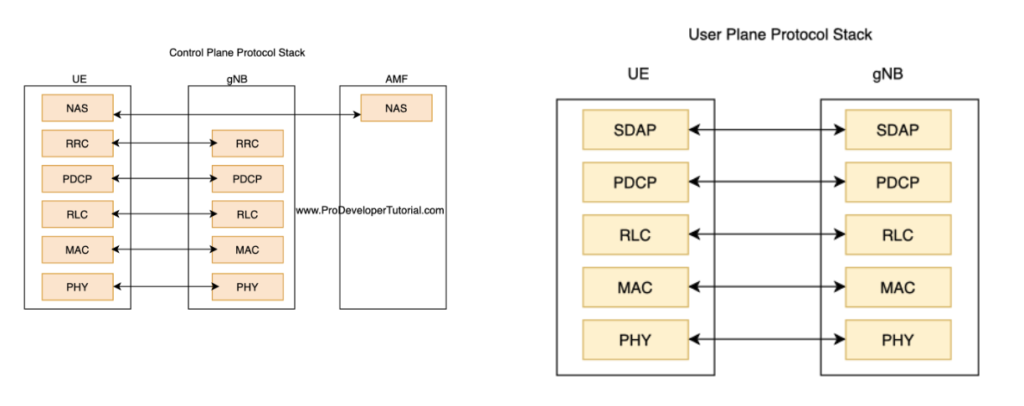
Control Plane vs User Plane for LTE
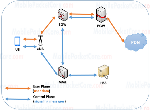
The nodes use the control plane, in order to exchange signaling messages between each other. The signaling messages controls the data session of the UE. using the signaling messages, the nodes can initiate, modify, or terminate the data session of the UE. While the nodes are using the user plane, in order to exchange the user data sent and received between the UE and the PDN.
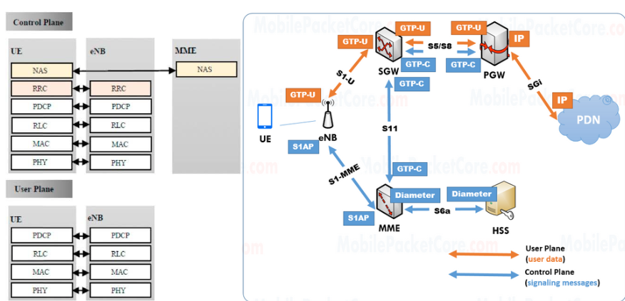
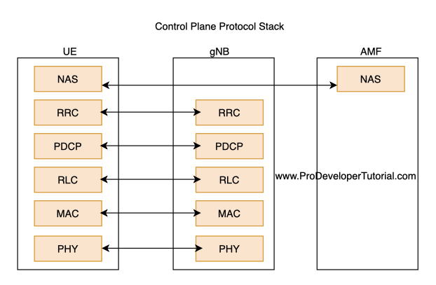
LTE Network Stack Implementation on Regular OSI Model
- Control Plane Stack encapsulates the User Plane stack.
- Control plane stack is used to setting up and tearing down the connections, while User Plane is used to actual data transfer
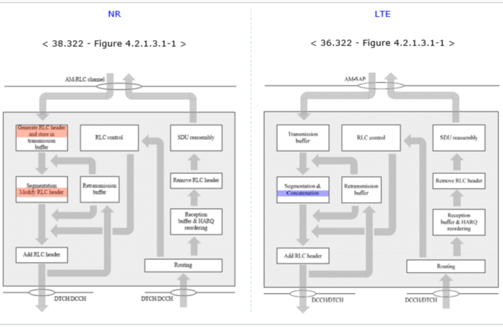
RLC (Radio Link Control)
It provides channel selection and transmission according to data package usage There are five different channel to select; BCCH, PCCH, CCCH, DTCH and DCCH. They are also called Radio Bearers. RLC has three different mode : TM(Transparent Mode), UM(Unacknowledge Mode) and AM(Acknowledge mode)
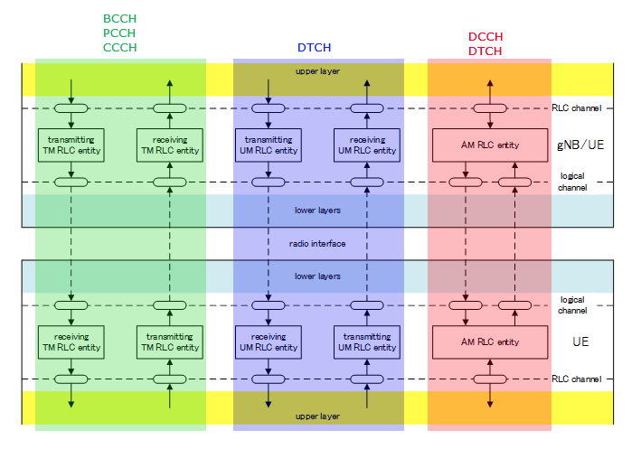
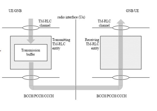
RLC – TM Mode
No RLC Header, Buffering at Tx only, No Segmentation/Reassembly, No feedback (i.e, No ACK/NACK)
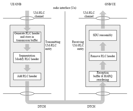
RLC – UM Mode
RLC Header, Buffering at both Tx and Rx, Segmentation/Reassembly, No feedback(i.e, No ACK/NACK)
i) Buffering the data and generate RLC Header.
ii) Segmentation (Split a big chunk into a multiple small chunk) and Modify RLC Header (Some field in RLC header should be changed based on the segmentation status)
iii) Add RLC header
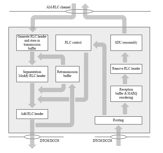
RLC – AM Mode
RLC Header, Buffering at both Tx and Rx, Segmentation/Reassembly, Feedback(i.e, ACK/NACK)
i) Buffering the data and generate RLC Header.
ii) Segmentation (Split a big chunk into a multiple small chunk) and Modify RLC Header (Some field in RLC header should be changed based on the segmentation status)
iii) Add RLC header
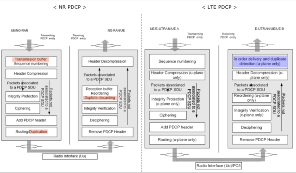
PDCP (Package Data Convergance P.) Layer
- It provides a interface between RLC and Higher U-Plane interface. (C-Plane and U-Plane Interface)
- In-Sequence delivery of Upper Layer PDUs at re-establishment of lower layer
- Elimination of duplicate of lower layer SDUs at re-establishment of lower layer for RLC AM
- Integrity Protection and Integrity verification of C-Plane Data
- For split and LWA bearers, routing and reordering.
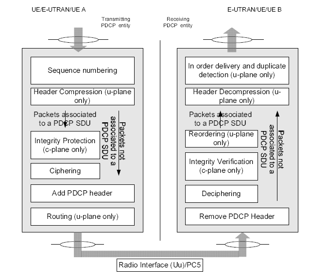
- Data coming into PDCP first go through “Sequence Numbering” Procedure. It means that PDCP add “Sequence Number” to each of incoming data block. Once it add ‘Sequence Number’, it has to manage the number.
- Header Compression: this applies only to U-plane data”. It means that Signaling Message does not go through this Header Compression.
- “Integrity/Ciphering” and the other one directly goes to the last step. Integrity Protection applies only to C-Plane data.
- Ciphering process. Ciphering applies both C-Plane and U-Plane Data. Ciphering process can also be disabled by applying EEA0.
- Eventually at the last step of transmission PDCP, a header is added and get out of PDCP layer.
RRC (Radio Resource Control) Layer
It provides a control mechanism to exchange informations on those configurations between communicating parties. The resulting implementation of this control mechanism is called RRC (Radio Resource Control).
RRC within each communicating party (i.e, within UE and Network) works as a control center for all of the lower layers within each system. The collection of all the lower layers within UE or base station is called ‘Radio Resource’ (i.e, resources required to make radio communication possible). The major role of RRC is to control(configure) all the Radio Resources (PHY, MAC, RLC, PDCP) to make it possible to communicate between UE and the base station (e.g, gNB, eNB, NB, BTS etc).
- RRC is a third layer describing the configurations of the lower stack and network.
- RRC is between UE parties and eNodeB
- It is needed for UE configuration by eNodeB
NAS (Non-Access Stratum) Layer
There are 2 types of procedures available in NAS layer:
1. EPS Mobility Management (EMM)
2. EPS Session Management (ESM).
NAS is responsible for handling the signaling messages between the UE and the core network, as well as for the control of the UE’s mobility and security. NAS is a network IP layer protocol and functional layer running between the User Equipment (UE) and the Core Network (CN)
EMM is used to provide support for UE to network related to eNB access, authentication and security.
1. EMM registered
2. EMM De-registered
EMM common procedures
* GUTI (Global Unique Temporary ID) reallocation
* Authentication
* Security mode control
* Identification
* EMM information
EMM specific procedures
* attach procedure
* detach procedure
* Tracking Area Update
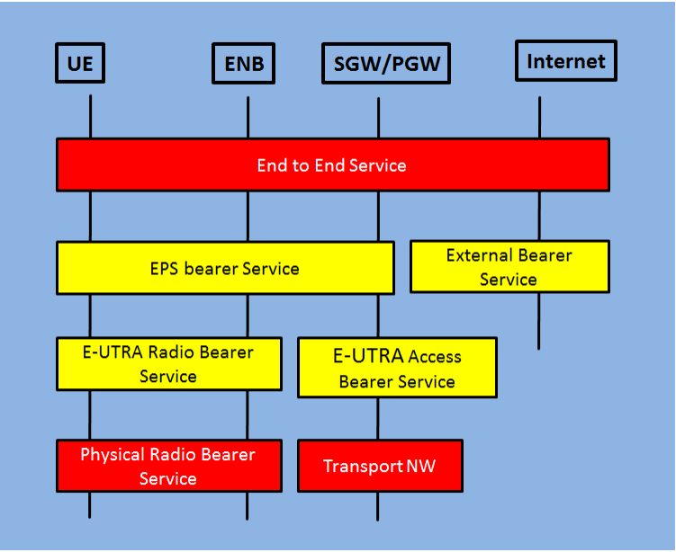
Bearer Concept
- The concept of Evolved Packet System (EPS) bearer in LTE exists for supporting end user data services. EPS bearer is defined between UE and Packet Data Network Gateway (P-GW) in the Evolved Packet Core (EPC).
- From the diagram, you can see EPS bearer is further sub-divided into an E-UTRA Radio bearer (between the eNodeB and UE over the radio interface) and E-UTRAN Access Bearer ( between eNodeB and SGW over the S1 – interface ) .
- There is one to one mapping between EPS Bearer , E-UTRAN Access Bearers and E-UTRAN Radio bearer.
- Each E-UTRAN Access Bearer is associated with a GTP Tunnel over S1 interface.
- Each E-UTRAN Radio bearer over the radio air interface is associated with RLC instance. Radio bearers represent different priority queues over the radio interface.
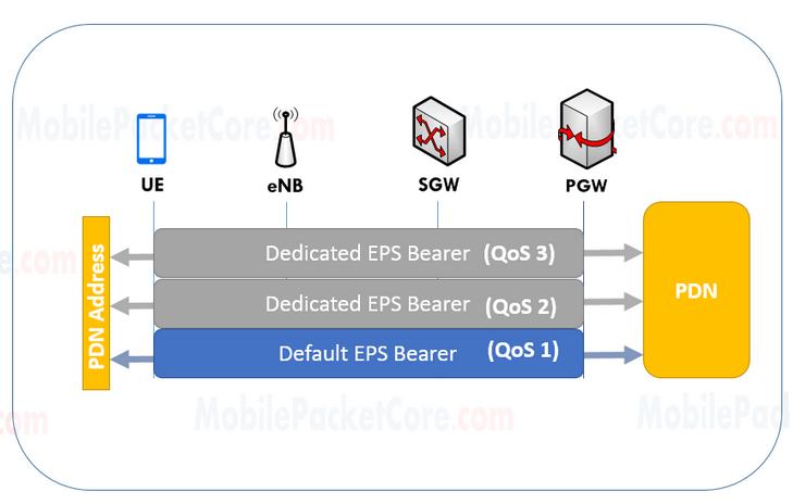
Default Bearer vs. Dedicated Bearer
- The EPS Bearer the network establishes during LTE attach procedure, is the default Bearer. While the network can established additional Bearers after the establishment of the default Bearer. Those Bearers are the Dedicated Bearers.
- The Dedicated Bearers are having the same PDN connection with the same IP address as the ‘Default Bearer’, but the QoS assigned to the ‘Dedicated Bearer’ is different than the QoS assigned to the ‘Default Bearer’.
- Therefore, the network creates a ‘Dedicated Bearer’, when there is an application or service that requires special QoS characteristics.
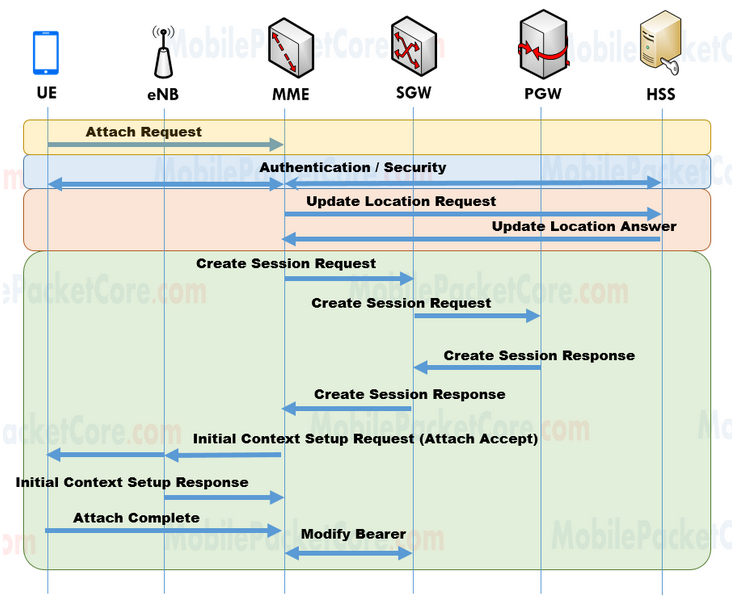
LTE Attachment
The attach procedure is the procedure in which the UE registers to the network, and creates the EPS Bearer between the UE and the PGW, in order to be able to send and receive data, to and from the PDN. After the LTE Attach Procedure ends, the following should be accomplished;
* The MME assigns the UE a GUTI.
* An EPS Bearer should be created between the UE and the PGW.
GUTI, is a temporary identifier that the MME assigns to the UE during the attach procedure. And, the UE uses this GUTI to identify itself to the network.
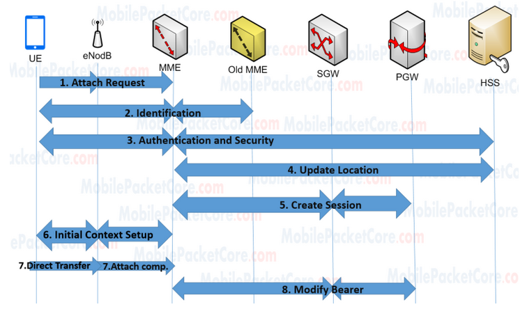
- The UE sends Attach request’ to the MME. This includes the GUTI of the UE received from the last attach, and the APN that the UE would Like to connect to.
- The MME performs authentication and security for the UE, in order to authenticate the UE, and to secure the messages exchanged between the MME and the UE.
- The MME sends ‘update location request’ to the HSS, this includes the MME ID of the MME. This is done because the HSS should always know the MME ID of the MME that currently serves the UE.
- The HSS replies with ‘Update location response. This includes the subscription information of the UE.
- Now the MME starts to create the EPS Bearer between the UE and the PGW by sending create session request’ to the SGW. This includes the APN that the UE would like to connect to.
- The SGW sends Create session request’ to the PGW including the APN the UE would like to connect to.
- The PGW assigns an IP address and a QoS profile for this EPS Bearer, and replies with Create session response, including the IP address and the QoS that the PGW assigned to the Bearer.
- The SGW sends Create session response’ to the MME including the IP address and the QoS that the PGW assigned to the Bearer.
- The MME sends ‘initial context setup request’ to the eNodeB, and this message includes ‘ Attach Accept’ message
- that the eNodeB should forward to the UE. The Attach Accept’ ,message includes the IP address and the QoS of the EPS Bearer.
- The eNodeB establishes the Radio Bearer with the UE, and replies the MME with ‘initial context setup response’
- And the UE replies the MME with Attach Complete’
- Finally the MME performs ‘modify bearer’ with the PGW, in order to complete the exchange of the EPS Bearer parameters.
GTP (GPRS Tunneling Protocol)
GPRS Tunneling Protocol (GTP) is a protocol used in mobile networks to enable the transport of data between the mobile devices and the core network. It is a protocol that is used to establish, maintain and terminate tunnels between the mobile devices and the core network.
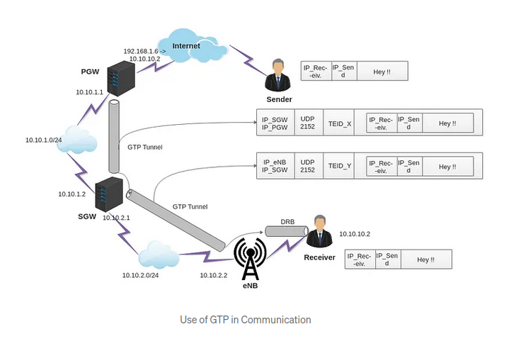
- It provides mobility. When UE is mobile, the IP address remains same and packets are still forwarded since tunneling is provided between PGW and eNB via SGW
- Multiple tunnels (bearers) can be used by same UE to obtain different network QoS
- Main IP remains hidden so it provides security as well
- Creation, deletion and modification of tunnels in case of GTP-C
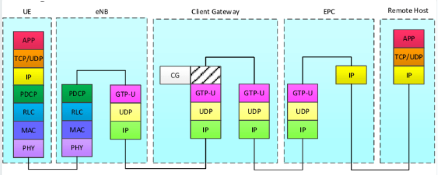
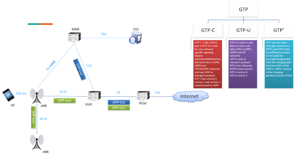
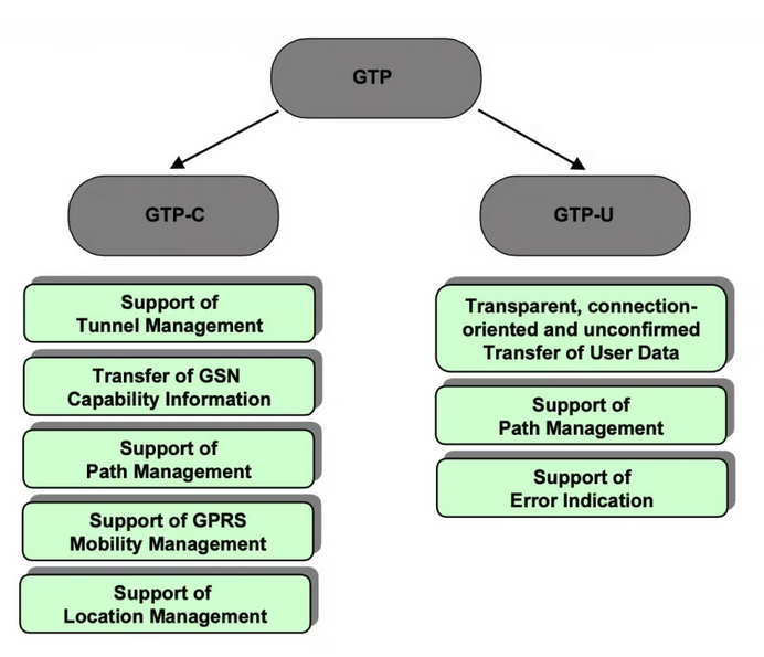
- The GTP protocol has two modes of operation: GTP-U (User Plane) and GTP-C (Control Plane).
- GTP-U is used for the transport of user data between the mobile devices and the external networks.
- GTP-C is used for the exchange of control information between the SGSN and the GGSN, such as the establishment, maintenance, and termination of tunnels.
- The GTP’ is used to transfer charging data to the Charging Gateway Function. GTP’ uses TCP/UDP port 3386. It is using same message structure with GTP-U and GTP-C
Functions of GTP
- Tunnel Establishment: The GTP protocol is used to establish tunnels between the mobile devices and the core network. The SGSN initiates the tunnel establishment process by sending a GTP-C message to the GGSN. The GGSN responds with a GTP-C message containing the TEID and the GSN address.
- Tunnel Maintenance: The GTP protocol is used to maintain the established tunnels. The SGSN periodically sends GTP-C messages to the GGSN to keep the tunnels open. The GGSN responds with a GTP-C message indicating the status of the tunnel.
- Tunnel Termination: The GTP protocol is used to terminate the established tunnels. The SGSN sends a GTP-C message to the GGSN requesting the termination of the tunnel. The GGSN responds with a GTP-C message confirming the termination of the tunnel.
- User Data Transport: The GTP protocol is used to transport user data between the mobile devices and the external networks. The GTP-U component encapsulates the user data in GTP packets and forwards them to the appropriate destination.
- Quality of Service (QoS) Management: The GTP protocol is used to manage the QoS of the data traffic in the mobile network. The SGSN and the GGSN exchange QoS information in GTP-C messages to ensure that the user data is delivered with the appropriate level of service.
Procedures of GTP-C
- Path management, i.e. the detection of communication failures at the paths (UDP/IP) providing GTP tunnels between SGSN and GGSN, detection of GSN restarts and also version control.
- Tunnel management, i.e. the creation, modification and deletion of GTP tunnels between an SGSN and GGSN.
- GPRS Mobility Management, e.g. to support the GPRS attach procedure or the Inter SGSN Routing Area Update procedure across the Gn interface.
- Optional Location Management,i.e.to handle location information about an MS if a GGSN does not support MAP signaling which means that the GGSN has no Gc interface.
Applications of GTP
- Mobile Internet: The GTP protocol is used to enable mobile devices to access the internet. The GGSN acts as a gateway that connects the mobile network to the external networks such as the internet.
- Voice over IP (VoIP): The GTP protocol is used to enable VoIP services in mobile networks. The GTP-U component is used to transport VoIP packets between the mobile devices and the external networks.
- Multimedia Messaging Service (MMS): The GTP protocol is used to enable the delivery of MMS messages in mobile networks. The GTP-U component is used to transport MMS packets between the mobile devices and the external networks.
- Location-Based Services (LBS): The GTP protocol is used to enable location-based services in mobile networks. The SGSN and the GGSN exchange location information in GTP-C messages to enable location-based services for the mobile devices.
Protocol Stack of GTP
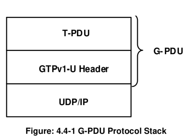
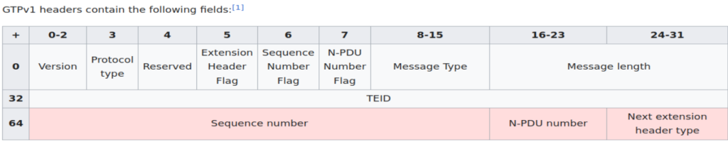
- Version field: determine the version of the GTP-U protocol. The version number shall be set to ‘1’ for GPTv1
- Protocol Type (PT): is used as a protocol discriminator between GTP (when PT is ‘1’) and GTP’ (when PT is ‘0’). GTP is described in slide
- Extension Header flag (E): For: 0′; Next Extension Header field is not present. For ‘1’, the Next Extension Header field is present
- Sequence number flag (S): For ‘0’, the Sequence Number field is not present For ‘1’; the Sequence Number field is present.For the Echo Request, Echo Response, Error Indication and Supported Extension Headers Notification messages, the S flag shall be set to ‘1’. Since the use of Sequence Numbers is optional for G-PDUs, the PGW, SGW, ePDG, eNodeB and TWAN should set the flag to ‘0’. the relaying entity shall set S flag to ‘1’ and forward the G-PDU (T-PDU+header). In an End marker message the S flag shall be set to ‘0’.
- N-PDU Number flag (PN): For ‘0’; the N-PDU Number field is not present, For ‘1’; the N-PDU Number field is present
- Message Type: indicates the type of GTP-U message.
- Length: indicates the length in octets of the payload.
- Tunnel Endpoint Identifier (TEID): identifies the receiving end side. The Echo Request/Response, Supported Extension Headers notification messages and the Error Indication message where the Tunnel Endpoint Identifier shall be set to all zeroes.
- Sequence Number: an increasing sequence number for T-PDUs is transmitted via GTP-U tunnels, when transmission order must be preserved.
- N-PDU Number: is used at the Inter SGSN Routing Area Update and some handover procedures. Meaning is depending on scenario
- Next Extension Header Type: defines the type of Extension Header that follows this field in the GTP-PDU.
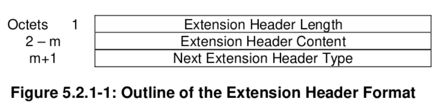
GTP-U Extension Header
- The expansion of QoS in the 5G network needs some additional parameters for each GTP packet. So, The GTP has to be extend due to these requirements.
- The Extension Header Length field specifies the length of the particular Extension header in 4 octets units.
- Bits 7 and 8 of the Next Extension Header Type define how the recipient shall handle unknown Extension Types. The recipient of an extension header of unknown type but marked as ‘comprehension not required’ for that recipient shall read the ‘Next Extension Header Type’ field
- If no such Header follows, then the value of the Next Extension Header Type shall be 0.
GTP-U Extension Header Types
- UDP Port: may be transmitted in Error Indication messages to provide the UDP Source Port of the G-PDU that triggered Error Indication.
- PDCP PDU Number: used to provide the PDCP sequence number of not yet acknowledged N-PDUs.
- Long PDCP PDU Number: long of PDCP PDU Number type.
- Service Class Indicator: identifies the service class indicator (radio resource allocation algorithm for LTE downlink). This information may be used by the A/Gb mode GERAN access for improved radio utilisation.
- RAN Container: transmitted in a G-PDU over the X2 user plane interface between the eNBs. It is capability meta Info.
- Xw RAN Container: transmitted in a G-PDU over the Xw user plane interface between the eNB and the WLAN Termination (WT).
- NR RAN Container: transmitted in a G-PDU over the X2-U, Xn-U and F1-U user plane interfaces, within NG-RAN
- PDU Session Container:shall be transmitted in a G-PDU over the N3 and N9 user plane interfaces, between NG-RAN and UPF, or between two UPFs. The expansion of QoS in 5GC means the UPF of gNodeB may need to set the QoS Flow Identifier per-packet, include delay measurements or signal that Reflective QoS is being used per packet, for this, you need to extend
GTP-U Signaling Message Types
- Path Management Messages
- Echo Request
- Echo Response
- Supported Extension Headers Notification
- Tunnel Management Messages
- Error Indication
- End Marker
- GTP-U signalling messages are used for user plane path management, or for user plane tunnel management.
- G-PDU is a vanilla user plane message, which carries the original packet (T-PDU). In G-PDU message, GTP-U header is followed by a T-PDU.
- A GTP-U Signalling message may contain several information elements. The TLV (Type, Length, Value) or TV (Type, Value) encoding format shall be used for the GTP information elements.
GTP-U Path Management Messages
- Echo Request: to the other GTP-U peer to find out if it is alive. When and how often an Echo Request message may be sent is implementation specific but an Echo Request shall not be sent more often than every 60 s on each path. This doesn’t prevent resending an Echo Request with the same sequence number according to the T3-RESPONSE timer. It optionally include Private Extension Information Element.
- Echo Response: shall be sent as a response to a received Echo Request. It include Recovery Information Element which is mandatory and Private Extension Element which is optionally
- Supported Extension Headers Notification: indicates a list of supported Extension Headers that the GTP entity on the identified IP address can support. It is sent only in case a GTP entity was required to interpret a mandatory Extension Header but the GTP entity was not yet upgraded to support that extension header. The GTP endpoint sending this message is marked as not enabled to support some extension headers. It include Extension Header Type List which is Mandatory.
GTP-U Tunnel Management Messages
- Error Indication: is sent when a GTP-U node receives a G-PDU for which no EPS Bearer context, PDP context, PDU Session, MBMS Bearer context, or RAB exists, the GTP-U node shall discard the G-PDU. GTP entities may include the “UDP Port” extension header (Type 0x40), in order to simplify the implementation of mechanisms that can mitigate the risk of Denial-of-Service attacks in some scenarios.Tunnel Endpoint Identifier Data I shall be the TEID fetched from the G-PDU that triggered this procedure.The information element GTP-U Peer Address shall be the destination address fetched from the original user data message that triggered this procedure
- End Marker: shall be sent after sending the last G-PDU that needs to be sent on a GTP-U tunnel. It is commonly used for handover procedure. It optionally include Private Extension Information Element
GTP-U Signaling Messages Information Elements
GTP-U Signalling message may contain several information elements. The TLV (Type, Length, Value) or TV (Type, Value) encoding format shall be used for the GTP information elements.
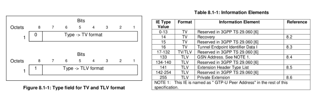
Information Element Types
- Recovery: indicates that the GTP entity that sent the echo request has restarted. The receiving GTP entity stores the new restart counter value received, replacing the the values previously stored.
- Tunnel Endpoint Identifier Data I: contains the Tunnel Endpoint Identifier used by a GTP entity
- GTP-U Peer Address: contains the address of a GTP. The Length field may have only two values (4 or 16) that determine if the Value field contains IPv4 or IPv6 address.
- Extension Header Type List: contains a list of ‘n’ Extension Header Types. The length field is set to the number of extension header types included.
- Private Extension: contains vendor specific information. The Extension Identifier is a value defined in the Private Enterprise number list in the most recent “Assigned Numbers”
Handling of Sequence Numbers of GTP
- The usage of sequence numbers in G-PDUs is optional, but if GTP-U protocol entities in these nodes are relaying G-PDUs to other nodes, then they shall relay the sequence numbers as well For all other cases.
- The sequence number is handled on a per GTP-U Tunnel (that is TEID) basis. During relocations and handovers.
- The notification of the sequence number is not necessary at the GGSN, but it is mandatory at the SGSN and RNC. The sequence number is handled on a per GTP-U Tunnel (that is TEID) basis.
- The Sequence Number in a signalling response message shall be copied from the signalling request message that the GSN or RNC is replying to.
- For GTP-U messages not having a defined response message for a request message, i.e. for messages Supported Extension Headers Notification and Error Indication, the Sequence Number shall be ignored by the receiver.
Reliable Delivery of Signalling Messages
- Each path maintains a queue with signalling messages to be sent to the peer. The Sequence Number shall be unique for each outstanding request message sourced from the same IP/UDP endpoint. A node running GTP may have several outstanding requests while waiting for responses.A request / response pair of messages shall have the same sequence number.
- The T3-RESPONSE timer shall be started when a signalling request message (for which a response has been defined) is sent. A signalling message request or response has probably been lost if a response has not been received before the T3-RESPONSE timer expires. The request is then retransmitted if the total number of request attempts is less than N3-REQUESTS times. (The wait time for a response (T3-RESPONSE timer value) and the number of retries (N3-REQUESTS) shall be configurable per procedure.)
- All received request messages shall be responded to and all response messages associated with a certain request shall always include the same information.
- Duplicated response messages shall be discarded. A response message without a matching outstanding request should be considered as a duplicate.
Error Handling of GTP
- Protocol Errors:
- GTP Message Length Errors
- Unknown GTP Signalling Message
- Unexpected GTP Signalling Message
- Missing Mandatorily Present Information Element
- Invalid Mandatory Information Element
- Invalid Optional Information Element
- Unknown Information Element
- Out of Sequence Information Elements
- Unexpected Information Element
- Repeated Information Elements
- Incorrect Optional Information Elements
- Path Failure:
- Restoration and Recovery
Protocol Error Handling
- A protocol error is defined as a message with unknown, unforeseen or erroneous content.
- That content shall be discarded without further processing and should log the event including the erroneous message and should include the error in a statistical counter.
- An information element, which is semantically mandatorily present but is omitted from the message, is treated as missing data. An information element, which is semantically mandatorily absent but is present in the message, is treated as unexpected data.
Path Failure Handling
- A path counter shall be reset each time a response is received on the path and incremented when the T3-RESPONSE timer expires for any message sent on the path.
- The path shall be considered to be down if the counter exceeds N3- REQUESTS.
- GTP shall also notify the upper layer of the path failure, so that PDP contexts associated with this path may be deleted
Restoration and Recovery
- All GSNs shall maintain in non-volatile memory a Restart Counter of local significance. A GSN that restarts shall change the Restart Counter value immediately after the restart procedure has been completed. The value shall be incremented by 1 modulo.
- Restart counter is attached to echo response message. it shall be set to zero by the sender and shall be ignored by the receiver. The Recovery information element is mandatory due to backwards compatibility reasons.
GTP Setup And Work
- To send a packet through a tunnel, first of all we should create the tunnel.This tunnel making process is done using control signals in GTP-C
- After the tunnel is formed, data sending and receiving process is done inside the GTP-U.
- GTP-C and GTP-U run on top of the UDP (User Datagram Protocol)
- IP in UDP tunneling is only used for GTP-U
- GTP-C packet is sent through the UDP port 2123
- GTP-U packet is sent through the UDP port 2152
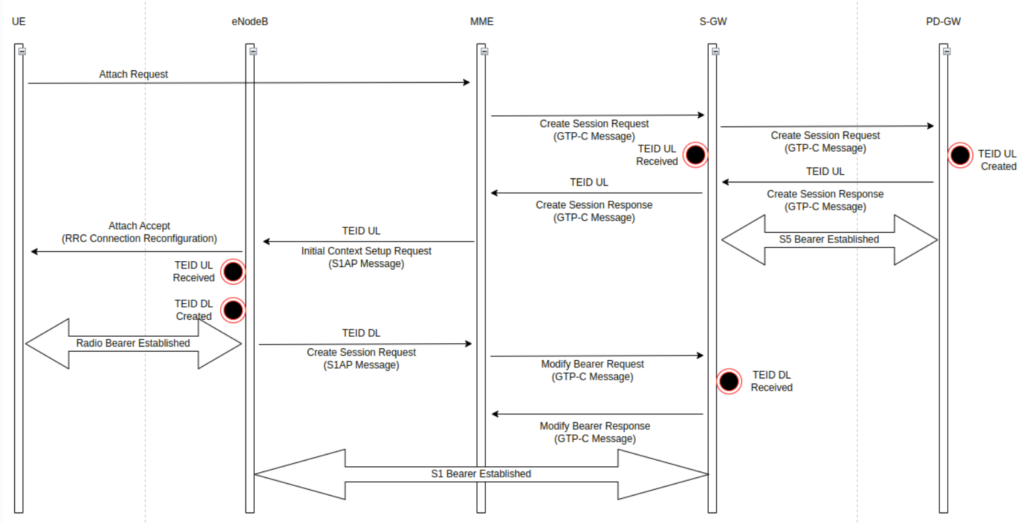
GTP Tunnel Creation
- S1 Bearer and S5 Bearer forms together GTP Tunnel in the Initial Attach Procedure of UE
- MME initiates EPS session and default bearer establishment procedure by sending Create Session Request message to the selected P-GW based on the Subscribed Profile received from HSS. and MME sends Create Session Request message to S-GW.
- P-GW allocates an UL S5 TEID to create a S5 Bearer (GTP-Tunnel) to S-GW, and returns Create Session Response Authorized QoS Profile message to S-GW.
- S-GW can be changed as UE moves to other cells. In that case MME delivers the UL S5 TEID to the changed S-GW so that the S-GW can transmit UL traffic to the P-GW.
- eNB allocates a DL S1 TEID to create a S1 GTP-U tunnel to S-GW eNB returns Initial Context Setup Response message to MME as a response to the Initial Context Setup Request message.
- MME delivers the S1 eNB TEID to S-GW by sending Modify Bearer Request message.
- S-GW receives the S1 eNB TEID and the DL S1 GTP-U tunnel has been created between eNB and S-GW
Handover
- Whether EPC Entities are Changed
- Intra-LTE Handover
- Intra-MME/S-GW Handover
- Inter-LTE Handover
- Inter-MME Handover:
- Inter-S-GW Handover
- Inter-MME/S-GW Handover
- Inter-RAT Handover:
- UTRAN to E-UTRAN
- E-UTRAN to UTRAN
- Whether EPC Entities are Not Changed
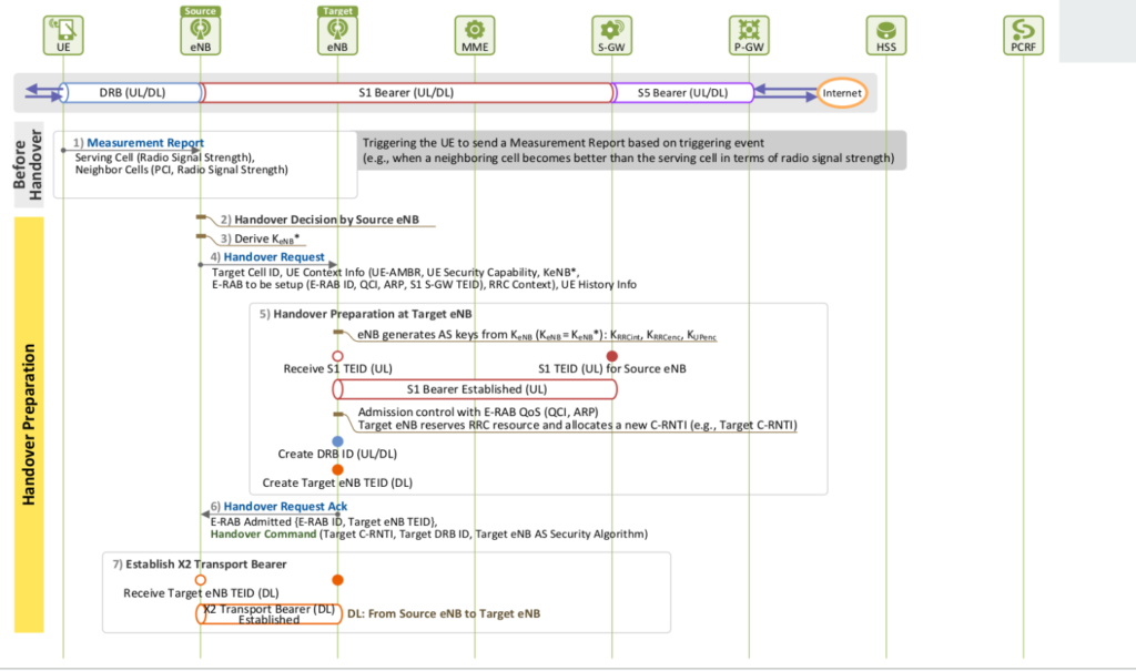
- X2 Handover
- S1 Handover
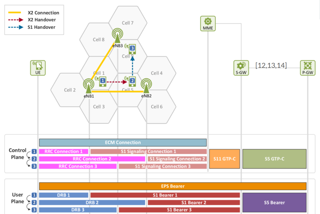
- X2 Handover: The X2 interface connects two eNBs. If there is an X2 connection between the eNB where the UE’s servingcell belongs X2 connection is available for handover, X2 handover is initiated. Once the handover is completed, the two eNBs communicate with each other to control the handover, without MME’s intervention.
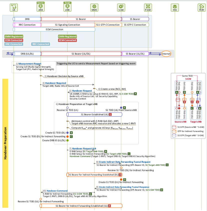
- S1 Handover: The S1 interface connects eNB and EPC If there is no X2 connection between a source eNB and a target eNB, then S1 handover is initiated. Once the handover is completed, the source eNB begins to communicate with the target eNB via MME to control the handover.
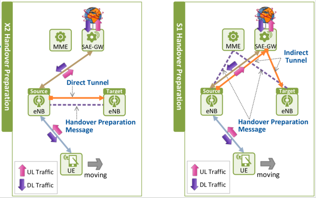
Handover – Preparation Phase
- The source eNB sends the user’s UE context to the target eNB to check whether the target eNB is capable of providing satisfying service quality.
- At this time, the DL packet forwarding bearer is either a direct tunnel connecting the two eNBs in case of X2 handover, or an indirect tunnel connecting all the three entities, i.e. the source eNB, S-GW and the target eNB, in case of S1 handover.
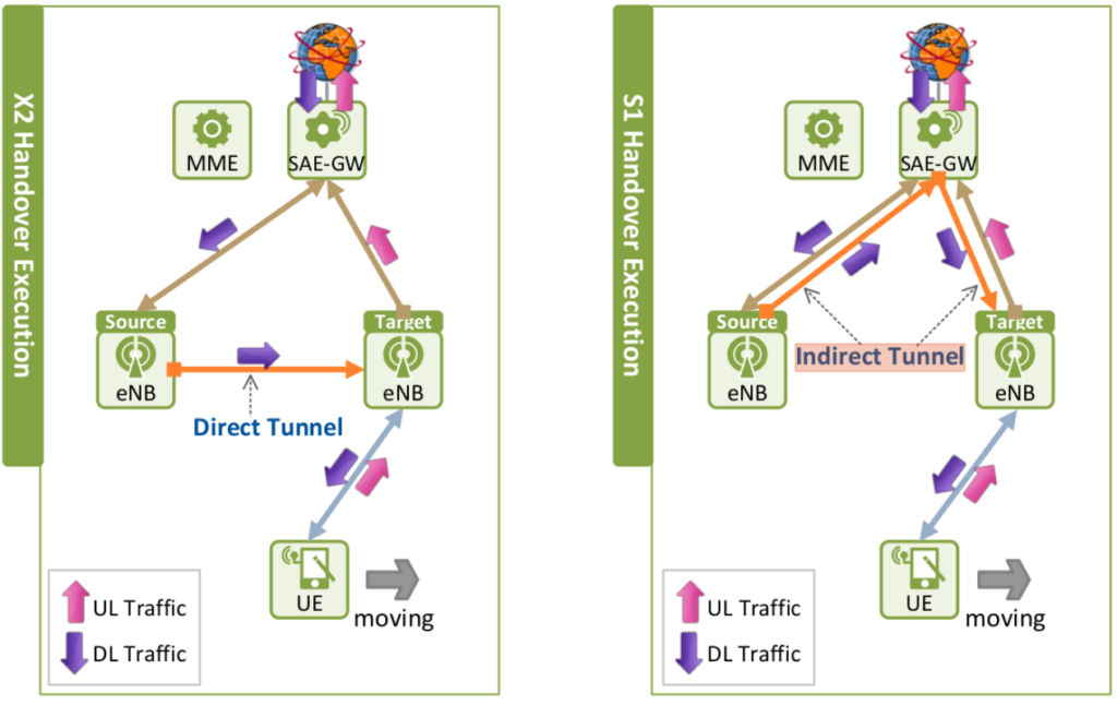
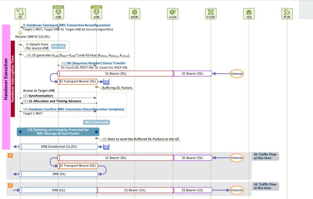
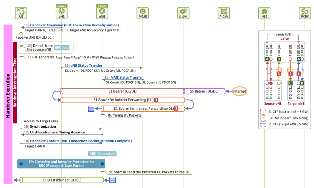
Handover – Execution Phase
- The UE disconnects the radio link from the source eNB, and connects it to the target eNB, accessing a new cell. Once the resources needed for packet forwarding between the two eNBs are allocated
- Once arrived at the source eNB, DL packets during the handover are forwarded to the target eNB through the forwarding bearer, and buffered there until the UE is completely accessed to the target eNB.
- UL packets coming from the UE are not forwarded until the UE is accessed to the target eNB successfully.Once the UE completes its radio access to the target eNB, the UL packets can be immediately forwarded to S-GW through the target
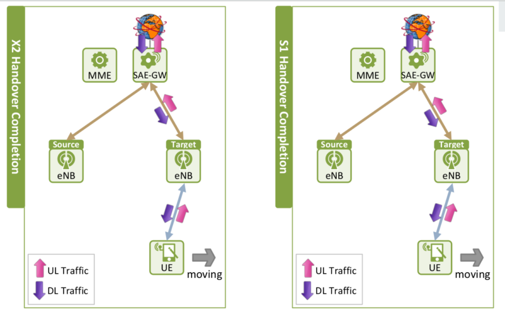
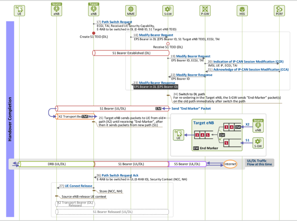
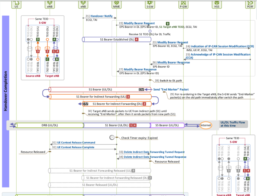
Handover – Completion Phase
- Once the UE completes its radio access to the target eNB successfully, the UE’s bearer path (DL S1 bearer) is now connected to the target eNB, instead of the source eNB. Once the path is switched, the forwarding bearer used in forwarding DL packets during the handover execution phase is released. As seen in Figure 7, both UL and DL traffic is delivered through the new bearer path once the handover completion phase is ended.
X2 Handover
S1 Handover
Detach
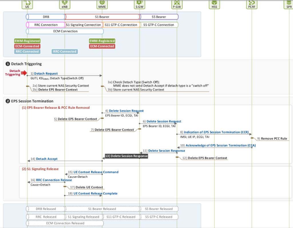
- Detach Case 1: UE-initiated Detach
- if UE is turned off
- if a USIM card is removed from UE
- if UE is attempting to use a non-EPS service
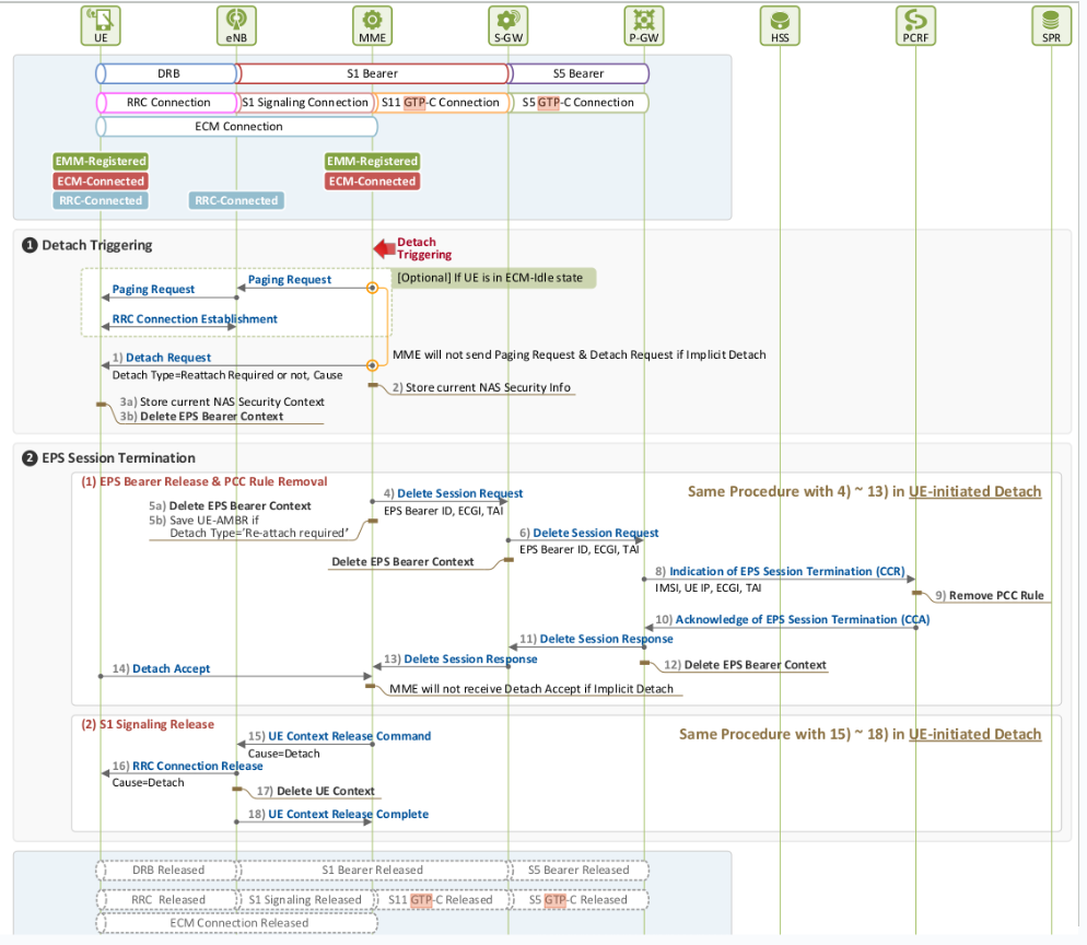
- Detach Case 2: MME-initiated Detach
- Explicit Detach
- for an operator’s O&M (Operation & Maintenance) purposes
- if re-authentication fails
- if it cannot provide the resources allocated to a user,
- Implicit Detach
- if it is not able to communicate with a user because of poor radio link quality
- Explicit Detach
- Detach Case 3: HSS-initiated Detach
- if the user profile provisioned in HSS is changed, and thus the one saved in MME also has to be changed
- if an operator is trying to restrict access by an illegal UE (e.g. a stolen device) to its network
UE-Initiated Detach
MME-Initiated Detach
HSS-Initiated Detach

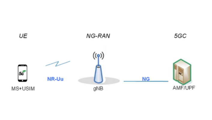
5G/NR Network Architecture
- The 5G can be schematically represented by the AMF/UPF entity: the User Plane Function (UPF), handling the user data and, in the signalling plane, the Access and Mobility management Function (AMF) that accesses the UE and the (R)AN.
- The 5GC architecture relies on a “Service-Based Architecture” (SBA) framework, where the architecture elements are defined in terms of “Network Functions” (NFs) rather than by “traditional” Network Entities.
- The Policy Control Function (PCF), that controls that the user data traffic does not exceed the negotiated bearer(s) capacities
- The Network Repository Function (NRF), which “controls” the other NFs by providing support for NF register, deregister and update service to NF and their services.
- The security-related NFs: Network Exposure Function (NEF), Authentication Server Function (AUSF), Security Anchor Functionality (SEAF) – see TechGuide “Security in 5G”
- The Network Slice Selection Function (NSSF) – see TechGuide “Slicing in 5G”
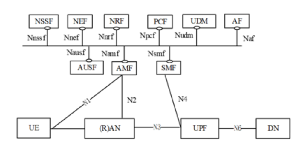
- The four entities already introduced, i.e.: the UE, the NG-RAN or (R)AN, the UPF and the AMF
- The (external) Data Network (DN), mostly in the User Plane
- The Application Function (AF), controlling the application(s) (with possible involvement also in the user plane)
- The Session Management Function (SMF), that handles the calls and sessions, and contacts the UPF accordingly
- The Unified Data Management (UDM), functionally similar to 3G and 4G’s HSS (and 2G’s HLR)
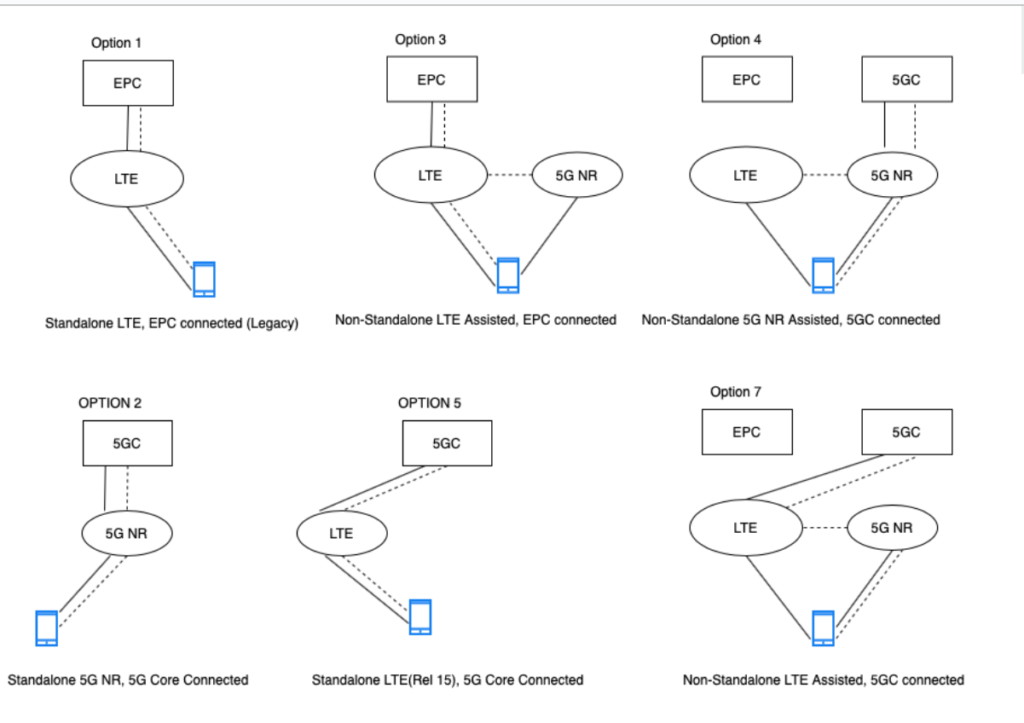
5G/NR Deployment Options
- Option 1: SA LTE Connected to EPC
- Option 2: SA NR Connected to 5G Core
- Option 3: NSA LTE-NR Dual Connectivity to EPC
- Option-3: The user plane data is sent to the 5G NR via the LTE RAN
- Option-3a: The user plane data comes to 5G NR directly from the EPC
- Option-3x: It is a combination of 3 and 3a. The user plane data will come from both EPC and eNB to gNB
- Option 4: LTE-NR Dual Connectivity to 5GC
- Option 4: The userplane traffic from eNB will route through gNB and goto 5GC
- Option 4a: The userplane traffic split will be made at 5GC and sent directly to eNB and gNB.
- Option 5: SA LTE under 5GC
- Option 7: LTE-NR Dual Connectivity to 5GC
- Option-7 — The user plane data is sent to the 5GC via the eNB
- Option-7a — The user plane data comes to eNB and gNB from 5GC
- Option-7x — It is a combination of 7 and 7a.
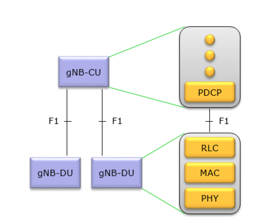
NR CU/DU Concept
- gNB internal structure is split into two parts called CU (Central Unit) and DU (Distributed Unit). these two entities are connected by a new interface called F1 (For the details of F1 Interface)
- This option will allow traffic aggregation from NR and E-UTRA transmission points to be centralized. Additionally, it can facilitate the management of traffic load between NR and E-UTRA transmission points.
- Fundamentals for achieving a PDCP-RLC split have already been standardized for LTE Dual Connectivity, alternative 3C. Therefore this split option should be the most straightforward option to standardize and the incremental effort required to standardize it should be relatively small
Control Plane vs User Plane Stack for NR
RLC – AM Mode 5G/NR Differences
PDCP (Package Data Convergence P.) Layer 5G/NR Differences
Even though the overall functionality of NR PDCP is very similar to LTE PDCP, there is slight difference between them. I highlighted the differences in the following diagram.
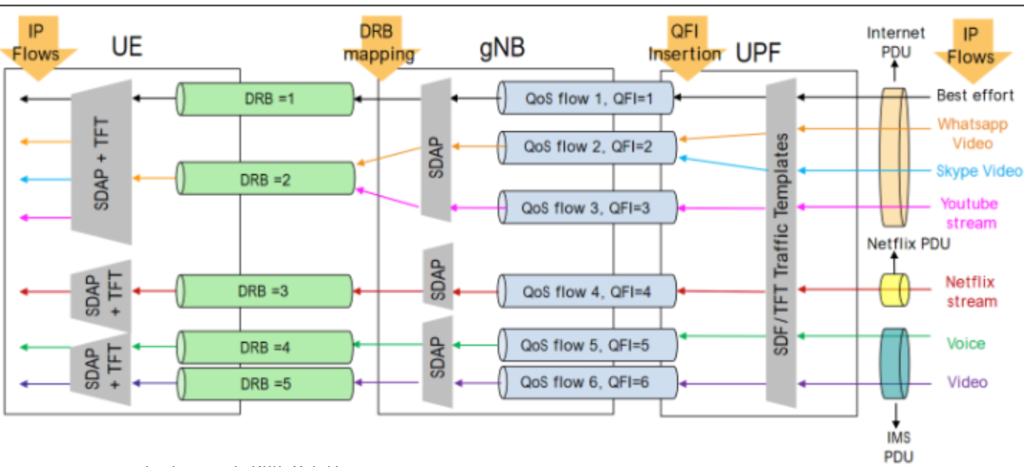
5G/NR SDAP (Service Data Adaptation Protocol)
- The 5G NR has introduce new mechanism to manage the Quality of Service via QoS flow and to handle QoS flow specifications has introduced a new Sublayer SDAP in air-interface procotols stack both at UE and gNB side.
- This layer is only applicable for 5G SA Architecture and not used in 5G NSA Architecture
- SDAP sublayer exists only in the user plane in both gNB&UE and is the highest layer within the RAN protocol stack
- From lower layers, SDAP expects in-sequence delivery of PDUs except when out-of-sequence delivery is configured by RRC at PDCP
- Apart from the transfer of user plane data, SDAP maps QoS flows to DRBs in both DL and UL
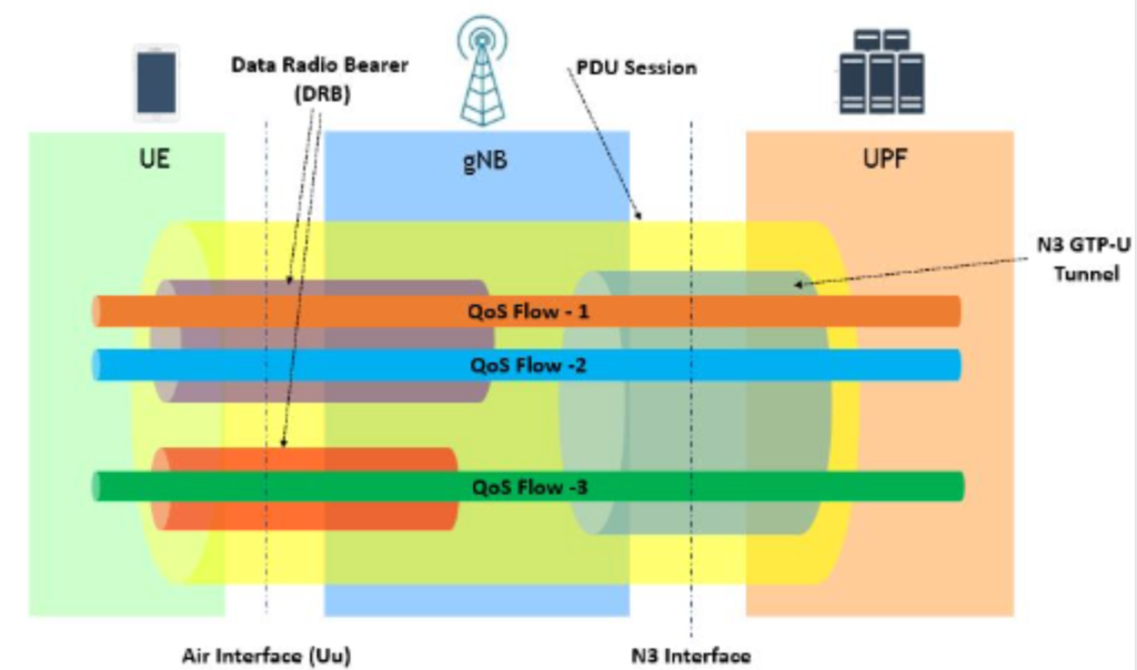
- The reason for the introduction of SDAP in NR is the new quality-of-service handling compared to LTE when connected to the 5G core. In this case the SDAP is responsible for the mapping between QoS flows and radio bearers
- The SDAP layer receives downlink data from the User Plane Function over NG-U interface. On NG-U interface DL user plane data is linked to a specific QoS Flow belonging to a specific PDU Session. This QoS Flow is identified using an identity within the ‘PDU Session Container’ which is included within the GTP-U header. The PDU Session is identified using the GTP-U Tunnel Endpoint Identifier (TEID). The SDAP layer maps each QoS Flow onto a specific Data Radio Bearer (DRB)
- With SDAP, Multiple QoS Flows can be mapped onto a single DRB:, or a single QoS Flow can be mapped onto a single DRB. QoS Flows belonging to different PDU Sessions arc mapped onto different DRB.
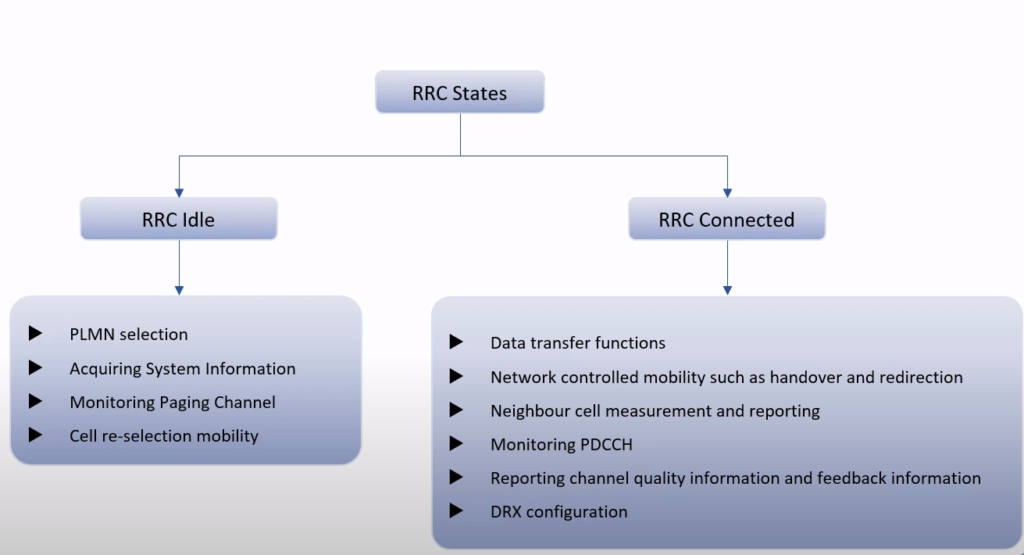
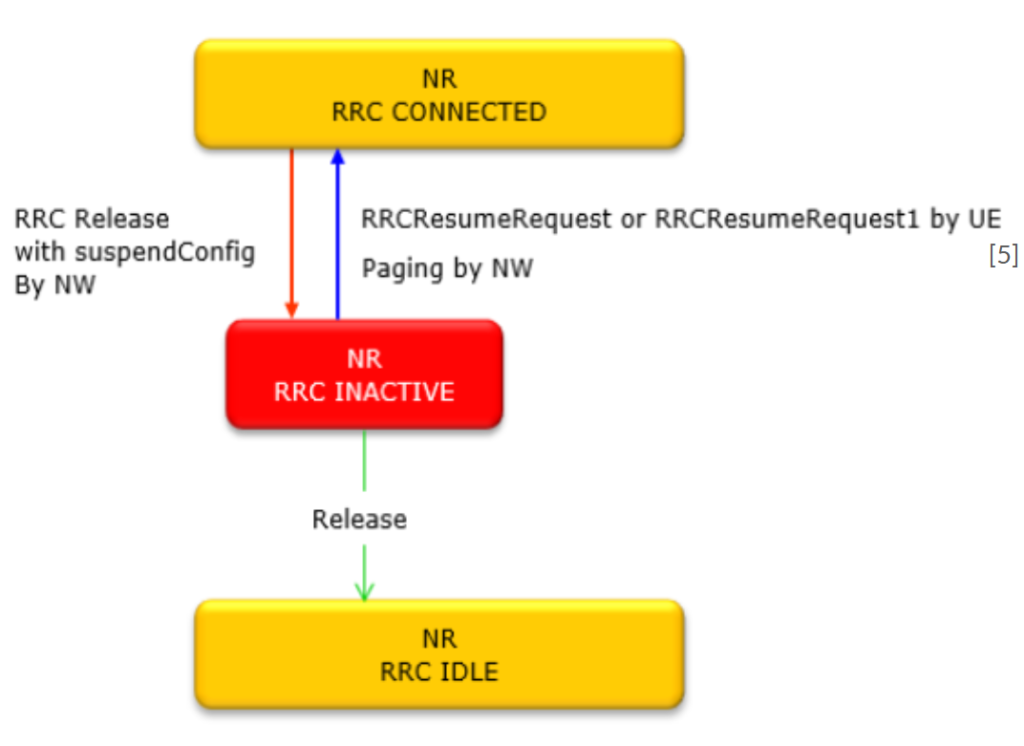
RRC (Radio Resource Control) 5G/NR Differences
Unlike LTE, in NR there is a addition RRC states between RRC Connected and Idle and Network/UE can optionally stay in INACTIVE state without completely releasing the RRC when there is no traffic and quickly switch back to CONNECTED states when necessary.
REFERENCES
- https://www.interviewbit.com/blog/lte-architecture/
- https://mobilepacketcore.com/lte-4g-network-architecture/
- https://www.sharetechnote.com/html/5G/5G_RLC.html
- https://www.sharetechnote.com/html/PDCP_LTE.html#Ex_DL_DTCH_PDCP_12BitSN_IP_Data_01
- https://www.sharetechnote.com/html/5G/5G_RRC_Overview.html
- https://www.prodevelopertutorial.com/lte-nas-layer/
- https://www.techtrained.com/what-is-the-bearer-concept-supported-by-the-eps/
- https://mobilepacketcore.com/lte-attach-procedure/
- https://subok-tech.com/introduction-gprs-tunneling-protocol-gtp/
- http://hongjoo71-e.blogspot.com/2015/06/volte-gtp-teid_17.html
- http://netsecinfo.blogspot.com/2009/06/lte-gtp-user-plane-enodeb-tutorial.html
- https://www.netmanias.com/en/?m=view&id=techdocs&no=10442
- https://www.netmanias.com/en/?m=view&id=techdocs&no=10451&xtag=emm-handover-lte&xref=emm-procedure-6-handover-without-tau-part-2-x2-handover
- https://www.netmanias.com/en/?m=view&id=techdocs&no=6286
- https://www.netmanias.com/en/?m=view&id=techdocs&no=6108&vm=pdf
- https://www.3gpp.org/technologies/5g-system-overview
- https://www.prodevelopertutorial.com/5g-tutorial-5g-overall-architecture-and-protocol-stack/
- https://www.sharetechnote.com/html/5G/5G_RAN_Architecture.html
- https://www.prodevelopertutorial.com/5g-tutorial-5g-deployment-options/
- https://www.techplayon.com/5g-nr-sdap-service-data-adaption-protocol/
- Etsi 3GPP PDSs